
 Short machine description and standard equipment
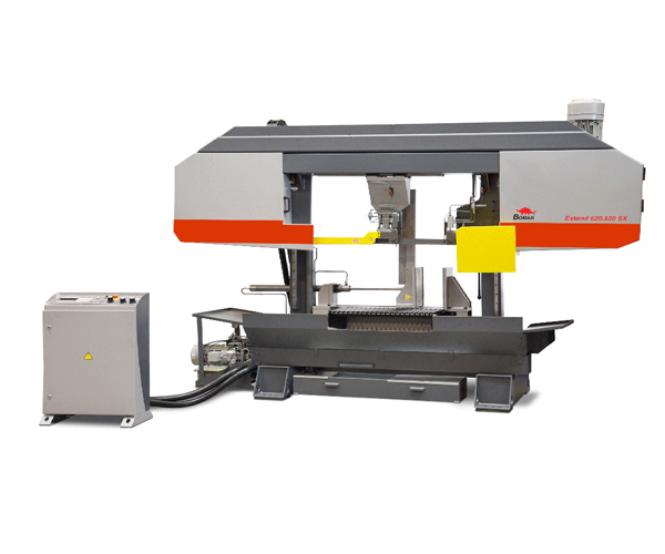
Metal band saw EXTEND 620.620 SX is a powerful hydraulic semiautomatic machine of two-column construction designed for series and highly productive cutting of material under 90° angle. Low-vibration saw cuts mean precision and long life. Polymer concrete offers the ideal damping characteristics for use in saw machines. On all Extend machines, the support,saw frames and columns are filled with a specially developed polymer concrete mixture. Coupled with pre-stressed, play-free, generously dimensioned linear guides, polymer concrete technology provides virtually vibration-free saw cuts with high cutting performance far above 100 cm2 per minute with M42 bimetal saw bands.
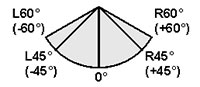
The ideal slope setting of the saw frame to the horizontal clamping surface depends on the shape of the material, and on the designated sawing process. The Extend series’ machine design allows this parameter to be set individually.
Machine allows to clamp and cut bundles of material with hydraulic bundle clamping device (see optional accessories) also. The machine is by default equipped with automatic cutting pressure regulation that together with 54x1,6 mm saw band ensures exact and straight cut. Frame diving into the cut is performed by linear roller bearing. The machine enables cuts of short scrap length. Peripheral speed of the saw band is regulated from the control panel by frequency converter in the range of 15-90 m/min.
Standard version
- Two-column construction.
- The frame is a steel weldment.
- Hydraulic full-stroke clamping vice
- Ergonomic design of machine, easy to operate, working bench height 780 mm
- Stepless adjustable saw blade speed 15-90 m/min with digital read out
- Stepless adjustable cutting feed and cutting pressure
- Automatic down-feed pressure control on the sawing blade
- Automatic pressure adaption according to material form
- Highly precise blade guides via carbide plates
- Slope setting 2° of the saw frame to the horizontal clamping surface
- Strong and reliable main drive motor with 7,5kW power
- Information regarding the state and process of semiautomatic cycle are shown on the LCD display as dialogues.
- Automatic machine’s shut-down if the saw-blade breaks or slackens
- State of the art controller with plaintext dialogue and membrane keyboard
- Comprehensive coolant system in the machine’s base
- Wide optional accessories for the machine
- Positioned freely users panel
Technical machine description
- Machine base The saw is constructed on a robust base in a height convenient for easy material handling. The base is filled with polymer concrete that together with machine’s construction supports absorption of vibrations and smooth running of the machine.
- Sawing head Saw frame is a steel weldment filled with polymer concrete and serves for exact guiding of saw band, its longer operating life and effective absorption of vibrations. Slope setting 2° of the saw frame to the horizontal clamping surface is a standard recommended for universal use of the saw machine, an ideal compromise between the 0° and 6° slopes. 6° slope we use in case, when profiles and carriers are separated, the cutting channel in the horizontal area of the material is held for a very short time. It is thus possible to use a finer saw band, and this considerably improves the cutting feed and precision. 0° slope we use for processing solid material and as a standard when using sliding tables with swivelling saw band guides for horizontal cuts.
- Sawing head guiding Frame is embedded on two robust columns in rolling linear guiding. Columns are tightly connected both on the top and on the bottom. Vertical frame movement is performed by two hydraulic stroke cylinders. Two columns are filled with polymer concrete for better absorption of vibrations and smooth running of the machine.
- Material clamping Material can be clamped by means of the full-stroke hydraulic clamping vice with possibility of vice pressure regulation as an optional accessory. The optional hydraulic bundle clamping device can be installed on the vice.
- Saw band tensioning The saw band tensioning is carried out hydraulically. A limit switch on the frame monitors the saw band defects, e. g. rupture, and immediately switches off the saw band drive in case of a defect. Saw band tension is shown on a hydraulic manometer.
- Saw band guideway The saw band is put on the moving wheels and in the place of cut directed by means of the guiding cubes. The professional tree-sided hard-metal guideway of the saw band guarantees high cut accuracy and long lifetime of the saw band. The left movable cube of the saw band guideway, embedded in the holder on the prismatic guideway, is automatically adjustable depending on width of the cut material.
- Saw band drive The saw band drive is performed by a powerful 7,5 kW electric engine and massive worm gearbox with possibility of speed change via frequency converter in the range of 15- 90 m/min. The display showing band speed is located on the control panel.
- Saw band cleaning Saw band cleaning is being performed by a chip brush securing smooth withdrawal of chips from the saw band, thus preventing chip penetration into the machine frame space and between the saw band and the wheels.
- Cooling The cooling equipment is a standard part of the machine. Cooling emulsion supply can be regulated by taps. The cooling emulsion is pumped directly from the machine base, where a 80 litres reservoir is installed. The saw band can also be equipped with an optional Microniser spraying oil onto the saw band, thus preventing leakage of the cooling emulsion outside of the band saw.
- Head down-feed into the cut Adjustment of head down-feed into the cut is controlled by a hydraulic throttle valve located directly on the control panel of the machine.
- Automatic cutting pressure regulation The cutting pressure regulation cube provides for a change of the sawing head down feed speed into the cut in dependence on shape and type of the material to be cut. Material’s resistance is transferred by means of a regulation’s needle in the regulation cube fixed on the guiding cube. The regulation cube adapts the down-feed speed without any intervention by the operator. Its design provides for very accurate speed changes in dependence on immediate cutting conditions of the given material to be cut. Automatic regulation is adjustable in dependence on material.
- Control element and controller All control elements are placed on the standalone control panel. Control of the machine has an user’s friendly structure and allows to new operators fast access thanks to text display and interactive system.
Working procedure
- Insert and align the material
- Adjust the saw frame to the necessary height
- Adjust the sensibility of the cutting pressure regulation
- Start the semiautomatic cycle by pressing the START-button
- Adjust the saw blade speed and/or readjust it
- The material is cut through and the saw frame moves up to the adjusted position
- Main drive stops and the vice opens
Possible automation
There are several possibilities for higher automation at the bandsaw EXTEND 620.620SX.
Powered conveyors with a NC-controlled measuring unit and a automatic feed reduction as well as stop solution, allow nearly fully automatic cutting even at longer length.
In combination with a feeding system it is possible to upgrade the machine to a fully automatic sawing line, exactly made to the need of the customers.
Technical datasheet
Cutting range:
 |
 |
 |
 |
 |
| 90°/0° | Ø620 mm | 620 x 620 mm | 620 x 620 mm | 620 x 620 mm |
| Minimal vice opening | 10 mm |
| Minimal length of rest piece | 30 mm |
| Working bench height | 780 mm |
| Saw blade dimension | 54x1,6 mm |
| Main drive power | 7,5 kW |
| Saw blade speed | 15-90 m/min. |
Optional Parts
- Equipment for clamping of bundles Support and main vice is equipped with hydraulic fulllift vertical clamping unit, installed on the pre-tightened linear rails.
- Vice clamping pressure regulation The fastening pressure on the main vice for cutting of thin wall tubes and profiles is regulated centrally on the control panel.
- Chip transporter Generously dimensioned clampshell chip transporter safely removes the chips away from the machine. Installation and connection points are integrated on the machine during manufacturing.
- Micro-spraying equipment – mikronizer The equipment for micro-spraying sprays the mixture of oil and air in an exact ratio to the saw belt teeth and on its side. The spraying nozzle is located directly on the guiding cube holder and provides ideal deposition of the mixture as well as minimal consumption of oil. The micro-spraying equipment is suitable for all types of material.
- Halogen working light Light cool source of light used for lighting of the working area could be directed anywhere to the required area using the flexible connection.
- Washing pistol Using its own pump the cooling liquid is transported to the washing gun with its own control button. The pressure is sufficient to remove all chips and dirt from the facing surfaces and from the saw base.
