
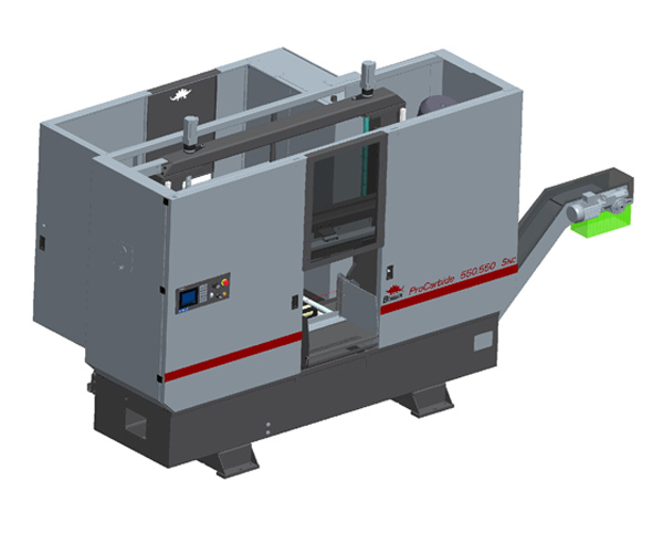
note: The picture of the band saw is for information only and may change due to technical modifications.
 Brief description of the machine
The machine ProCarbide 550.550 SNC is a fully automated CNC controlled production band saw, a two column version. The saw has 750 mm feeding on a linear guide, a hydraulic vice with full lift and has a comfortable CNC control panel with a big colour display.
Features
- polymer concrete technology to minimise vibration in the saw frame, columns and base of the machine
- feeding controlled by a servomotor and a ball-type screw
- feeding slide floating on linear segments, with a linear guide
- saw frame supported on a precise guide, pre-loaded without clearance
- continuously adjustable cutting speed 30-230 m/min
- continuously adjustable feeding and sensitivity of the cutting pressure right regulated at the control panel
- automated regulation of the cutting pressure adapting to the material form and the corresponding cutting channel
- hydraulic stress-loading of the saw belt with automated pressure relief, when the saw turns off
- electrically driven chippings brush
- continuous roller track up to the main vice
- hardened stress-loading ledges on the main vice and on the feed vice
- divided main vice stresses the material before and after the saw belt
- modern CNC equipment with a big colour display and dialogue controlled system with a user friendly message text
Technical description
- Base of the machine A stable, rigid, welded construction filled with polymer concrete. Conveyor belt for chippings can be attached.
- Saw frame A stable, rigid, welded construction in a shell construction, filled with polymer concrete to ensure a silent operation and precise saw cutting.
- Columns and guides in the saw frame The saw frame is guided on two columns filled with polymer concrete and on a linear guide pre-loaded without clearance on each column. The columns form a solid frame across the machine base and the saw frame.
- Main vice The main vice has a large hydraulic cylinder for complete feed sliding and a polished guide with low wear-n-tear. The main vice is divided in the centre, so the machined element is stress-loaded before and after the saw belt. The chucking jaws have hardened grooved inserted ledges before and after the saw belt.
- Feed vice The feeding vice is floating on linear segments to balance any uneven material and has a large hydraulic press as well as ground, low wear-n-tear guide. The chucking jaws have hardened, grooved inserted ledges.
- Feed movement unit The feeding slides through a ball-type screw with no clearance, controlled by a servomotor. The feed movement length is 750 mm for a single move. Positioning is ensured by a precise magnetic measurement system along the whole feeding length.
- Stress-loading of the saw band The saw bend is stress-loaded over the hydraulic cylinder. The stress pressure is pre- set for the optimum stress of the saw band. When the machine is idle, the stress is released after a pre-set time, to lower the wear-n-tear of the saw band.
- Guide of the saw band The side guide of the saw band goes across the precisely set and polished guide plates made of hard metal. The rear component of the saw band goes across hard- metal cylinders of low wear-n-tear. The left guide arm is automatically adjusted with the main vice and it ensures the smallest clearance between the machined item and the saw band guide to ensure the highest cutting performance.
- Saw band drive The saw band is driven by a frequency-controlled 15 kW industrial engine and a large worm gearbox. The saw band speed 30-230 m/min can be continuously adjusted at the control panel.
- Saw feed movement and the cutting pressure The saw is moved by a ball srew and it is set at the control panel. The cutting pressure is permanently monitored by the automated regulator of the cutting pressure, adjusted to the material form. The cutting pressure regulator sensitivity can be adjusted individually.
- Hydraulic equipment The hydraulic aggregate is large and well accessible, located on the opposite side of the machine. The valve block of the hydraulic equipment is located separately to facilitate easier maintenance and adjustment.
- Controls and servicing elements All the servicing elements of the band saw are located at the same place in a user- friendly control panel. The control panel can be freely turned, it is right on the front side of the machine in an ergonomic height. The machinery is user-friendly, easy to understand and it is fast to learn thanks to clear message texts in the large colour display and the easy-to-understand dialogue system.
Work procedure
- set the saw frame to the needed lifting height
- insert and stack the material
- set the cutting pressure regulator sensitivity
- set the length and quantity of piece cutting or select a cutting programme
- start the automated cutting cycle
- set or adjust the saw band speed
- the cutting cycle shall repeat until the programmed quantity is achieved
Description of optional accessories
- A5.1. Automation for individual cutting Automation of individual cutting allows productive, fully automated separation of individual pieces. The diameter of the material and the length of the piece cutting is entered in a display, then the material gets inserted into the feeding area. A laser sensor detects the beginning of the material, so only the desired length of the piece is cut off. Unless further piece cutting is wanted, the material gets released again.
- Control of diverging cuts Each saw cutting is monitored and if it breaches the preset tolerance, the cutting is suspended. The running programme interrupts and an alarm control light or a display message gives a warning.
- Material selection system In the display you select a group of materials and set the form and diameter of the cut material. The machine adjusts the cut feeding, cut pressure and saw band speed automatically to match the currently inserted saw band. If the currently inserted saw band is unsuitable, the display shows a warning message.
- Stress-loading equipment of the cluster The feeding vice and the main vice have a hydraulic vertical loading unit for full lifting. The loading weight of the vertical stress-loading unit are supported on pre-loaded linear guides.
- Stress-loading pressure regulation To cut thin-wall tubes and profiles the stress-loading pressure for the feeding vice and main vice is regulated centrally from the control panel.
- Conveyor belt for chippings A generously constructed conveyor belt with grab-type bottom transports the generated chippings out of the machine. The installation and connection is already integrated within the machine, provided by the producer.
- Remote maintenance system The customer’s existing internet connection allows the error messages to get to the service centre in the plant. The service centre analyses the received data and ensures a speedy and straightforward solution of the error.
- Micro-spray equipment “Micronizer“ The micro-spray equipment uses a mix of air and oil to spray precisely adjustable minimum lubrication oil to the cogs of the saw band and the rear side of the band. The spray nozzle is right of the band guide arm and it ensures an ideal spreading and minimum oil consumption. The micro-spray equipment “Microniser” is suitable for all materials.
- Halogen work light A source of bright cold light to enlighten the working area of the band saw. Due to a flexible connection it is easy to set-up for the required area.
- Pistol for chippings removal Using its own pump a coolant is loaded into the spray gun with a control button. The pressure is enough to rinse away the chippings and impurities from the operating surface and base.
Technical data
| Cutting capacity | 550550x550550x550 |
| Material space height | 800mm |
| Max length of feeding movement Single feed movement | 750mm |
| Smallest cut diameter | 10 mm |
| Saw band dimensions | 67 x 1,6mm |
| Saw band speed | 30-230 m/min |
| Saw band drive performance | 15 kW |
|
Electronic supply line data Supply voltage |
3 x 400V, 50Hz, TN-C-S |
