
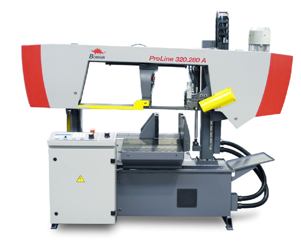
Note : The illustration is only informative and shows a machine of a similar construction in a manual version.
Brief description of the saw and standard equipment
The ProLine 320.280 ANC machine is an automatic band saw of a double-column construction with CNC control for perpendicular cuts. It is designed for cutting either individual pieces or material in bundles using a hydraulic bundling machine (optional accessory). With the maximum length of an individual feed 600 mm it belongs to standard automatic machines of the ProLine series. Its standard equipment includes automatic downfeed pressure regulation and a 27 mm high band, ensuring precise and straight cuts. The saw is easily controlled from an independent control panel.
Standard equipment
- Double-column construction
- Saw arm laid on a preloaded linear guiding on one side and on an auxiliary guiding on the other side
- A hydraulic full-stroke main clamping vice and a feeding vice
- Continuously settable saw band speed within the 20-120 m/min range
- Hardmetal band precision guide ensuring precise cutting
- Continuously adjustable saw arm downfeed and pressure
- Automatic downfeed pressure regulation dependent on the processed material resistance
- Saw band running through the middle of the fixed vice
- Automatic shutdown of the machine due to a non-tensioned or broken saw band
- Powerful and reliable 2.2 kW engine of the saw band drive
- Up-to-date control with text display and a membrane keyboard
- Information on the machine status and the automatic cycle course on an LCD display in the form of a dialogue
- Large hydraulic unit
- Precise feeding vice positioning through a sensor on a magnetic tape
- Driven cleaning brush of the saw band
Technical description
- Machine pedestal A welded, torsion-resistant structure with an integrated cooling liquid tank and a removable chip pan.
- Saw arm A solid welded, vibration-resistant structure, ensuring a very quiet operation and precise cutting. The arm is tilted against the material bearing surface at a 2° angle, thanks to which a very short cutting channel may be made in profiles and beams. Thanks to the short cutting channel finer toothing may be used, and thus a higher downfeed speed may be set. Prolonged saw band lifetime, significantly shortened cutting times and increased cutting precision.
- Columns and saw arm guiding The saw arm is guided through two robust columns and laid on a preloaded, clearance-free linear guiding on one side and on an auxiliary guiding o the other side. The columns together with the saw arm form a stable unit.
- Arm height limitation The arm position height may be set manually directly on the scale which shows the arm stroke height. The arm position in the required height after the cutting completion is secured by shifting a movable cam (connected with the arm movement) along the scale and by its consequent contact with a terminal switch.
- Material clamping and feeding The material is fed by a movable vice, which downfeeds the material in a required length, and then clamped by the main clamping vice. The material is clamped in both vices continuously with hydraulic cylinders. To thin-walled materials vice pressure regulation may be applied, see special accessories. The maximum length of the material feeding in one stroke is 600 mm. The precise position of the feeding vice is detected by a linear magnetic measuring system with high resolution and accuracy of 0.1 mm. The sectional jaws of the main clamping device enable the material to be clamped both before and behind the cut.
- Band tensioning The saw band is tensioned manually. The band tensioning, and also its possible breaking is electronically monitored. The clamping force may be set directly on the saw arm with precise indication on the pressure indicator.
- Saw band guiding The saw band is set on running wheels and directed in the place of cutting with guiding cubes. A professional three-sided hardmetal band guide ensures high cutting precision and the band’s long lifetime. The left movable cube of the band guide, laid in a holder on prismatic guiding, is manually adjustable according to the processed material width.
- Saw band drive The saw band is driven by an industrial 2.2 kW motor, controlled by a frequency convertor, and by a robust worm-gear unit. The saw band speed may be changed continuously on the control panel within the 20-120 m/min range.
- Downfeeding and downfeed pressure regulation The arm downfeed is controlled hydraulically through a hydraulic cylinder and is set on the control panel. The downfeed pressure is permanently monitored by automatic downfeed pressure regulation and adjusted to the material shape. The downfeed pressure regulation sensitivity may be set individually depending on the material shape and quality.
- Hydraulic system The sufficiently-dimensioned hydraulic unit is located in the front part of the machine where it is easily accessible. The valve block of the hydraulic system is located separately so that it could be simply maintained and adjusted.
- Control elements and control system All control elements of the band saw are located on the freely-adjustable control panel. Data are entered in the form of a dialogue via an easy-to-control membrane keyboard and display. There are three modes to be selected from: a manual control mode, a service menu of the machine setting, and an automatic mode for setting the cutting parameters. Error and status messages are showed together with a text on the display. The control system has an understandable structure and thanks to the text display and dialogue system provides an easy access for new users.
Operating procedure
The operating procedure is automatic. The saw band is set above the material. After the length and number of pieces have been programmed and the START button pressed, the material is fed by the feeding vice and clamped by the main hydraulic vice, the band motor starts up and the arm starts downfeeding. Meanwhile, the feeding vice moves to the material feeding rear position. After the cutting is completed, the arm moves to the preset top position, the main vice opens up and the feeding vice feeds the required length of the material. Then the working cycle repeats. The arm downfeed speed is regulated hydraulically with a throttle valve.
Technical data
Cutting ranges
 |
 |
 |
 |
 |
|---|---|---|---|---|
| 90/0° | Ø280 mm | 320 x 280 mm | 320 x 280 mm | 280 mm |
| Minimum vice opening | 5 mm |
| Material loading height | 780 mm |
| Maximum weight of fed material | 2,180 kg |
| Saw band dimensions | 3,800 x 27 x 0.9 mm |
| Drive output | 2.2 kW |
| Cutting speed | 20-120 m/min |
| Dimensions: width length height |
1,950 mm 1,950 mm 2,000 mm |
| Total height | 1000 kg |
Description of available accessories
- Hydraulic bundle device for both vices Necessary equipment for cutting in bundles. Additional top pressure jaw is mounted on main and feeding vice jaws and makes possible proper fixing of more then one piece of material – prevents material spontaneous movement up. Fixing and positioning of the top pressure is hydraulic and is done together with main vice and feeding vice maniupulation.
- Hydraulic blade tensioning indicator For easy and correct blade tensioning to recommended values could be machine equipped with hydraulic indicator placed on the tensioning system of the machine. By this device could be prevented over-tensioning or low-tenstioning of the blade and it has direct influence for blade lifetime.
- Automatic first cut transaction Without this equipment is necessary to cut in automatic mode the first piece of material for alignment to be able to state material begining. This piece should usually be discarded because of wrong length and shape. This device enables to scan begining of the material by laser beam and after material infeed to cut first piece with big accuracy. After the first piece checking this could be counted into the total amount of cutted pieces or – if it does not fit – to be discarded. This device is very useful for expensive materials cutting
- Micronizer – mist lubrication is device that creates oil greasing mist with very precise dosing of oil and air mixture. This mixture is applied directly on the blade by nozzles and makes greasing and cooling down. Advantage is that this prevent outflow of the coolant water out from the cutting space of the machines, mainly during profile material cutting. Also very suitable for materials where is not possible any contact with standard water coolant. Usage of Micronizer is full-value kind of cooling and greasing.
- Third coolant inflow used for big sized material, where position of the guiding cubes is too wide and consequently is not possible proper greasing and cooling on the whole cut duration. Third, easily aiming and adjustable coolant supply with a nozzle ensure sufficient greasing and cooling of the blade directly in the middle of the cutting material.
- Halogen light in case of insufficient lighting of the working space is possible to use this adjustable white additioinal light. This makes possible easier material manipulation, setting or checking of the cut quality.
- Pistol for machine cleaning Powerful rinsing pistol with long input hose makes possible easy cleaining of the machine after finish of the working time. Even the most inaccessible places of the machine could be easily cleaned.
- Tenzomat – blade tension meter is device for adjustment of the correct blade tension. By help of this is very easy to set tension to recommended values by the help of analogue indicator. That prolongs blade lifetime and enables higher speed and better quality of the cut. Tenzomat is supplied in a wooden box.
- Pressure regulation for vice/both vices In some cases like thin-wall material cutting, non-standard shaped material or full material of big diameter, is necessary to change the pressure of fixing vice. This device enables to choose optimal fixing pressure so there is no danger of material or vice damage.
- Straight cut deviation gauge For material cutting in automatic mode is very important quality and cut straightness constant check. Once the blade is not sharp properly and could make a wrong straightness – deviation gauge stop the machine and call operators attention.
- Swarf remover Certain types of our machines could be equipped with swarf remover. This device is very useful for bigger diameters of full material cutted on both automatic and semi-automatic machines. Advantage is removing of swarfs from the cutting place and their concentration in a box. It makes possible subsequent ecological processing of the waste.