
Note: The illustration is only informative and shows a machine of a similar construction in a manual version.
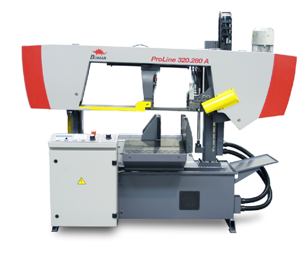
Brief description of the saw including equipment
Workline 410.280 DG is a gravitational band saw with a two-way swivelling arm. Continuous cutting range from - 60° to +60°. The Workline 410.280 DG model is equipped with manual pressure vice with special clamping system Quick-Move and fast clamping device.
Standard equipment of the machine
- Mitre cut from -60° up to + 60°
- Large, easy-to-read angular scale
- Special pressure vice with Quick-Move system
- Continuously settable saw band speed within the 20-120 m/min range
- Continuously adjustable saw arm downfeed
- Hardmetal band precision guide
- Powerful 2,2 kW industrial engine
- Simple, comfortable operation
- Removable chip pan with a separating sieve
- Construction complying with valid CE standards and safety regulations
Technical description
- Machine pedestal A welded, torsion-resistant structure with an integrated cooling liquid tank.
- Saw arm A stable arm of a shell construction, vibration-resistant, ensuring a very quiet operation and precise cutting.
- Saw arm mounting The saw arm, mounted on a vice bracket, is laid in wear-resistant, precision guiding sleeves.
- Mitre cuts setting The machine provides continuous two-way swivelling within the -60° to 60° range. Simple manual setting of mitre cuts directly from the operator’s position. The saw arm is mounted on a swinging bracket fitted with an easy-to-read angular scale. For performing mitre cuts the vice is manually moved to the sides according to the arm angle.
- Vice The vice is equipped with a currently developed pressure system in which the material is always clamped against both vertical and horizontal bearing surface. “Quick-Move“ system means that the clamping jaw is freely-adjustable and enables easy readjustment of the clamping vice within seconds when the material is changed. The movable clamping jaw is guided on hardened rails resistant to wear.
- Saw band tensioning The saw band is tensioned manually. The band tensioning, and also its possible breaking is electronically monitored.
- Saw band guiding The saw band is set on running wheels and directed in the place of cutting with guiding cubes. A professional three-sided hardmetal band guide ensures high cutting precision and long lifetime of the band. The left movable cube of the saw band guide, laid in a holder on prismatic guiding, is manually adjustable according to the processed material width.
- Saw band drive The saw band is driven by a 2,2 kW frequency-controlled industrial engine and a sufficiently-dimensioned worm-gear unit. The saw band speed may be changed continuously on the control panel within the 20-120 m/min range.
- Down feeding regulation The arm down feed is gravitational controlled by hydraulic valve placed on the main control panel.
- Control elements All control elements of the band saw are located on the ergonomically control panel. Control buttons are clearly and simply labelled.
Operating procedure
- The saw arm is manually adjusted to the required stroke height.
- Material is inserted and aligned.
- Material is clamped.
- The saw arm is adjusted to the required angle.
- The vice is moved, if necessary.
- The movable guiding cube is adjusted to the minimum distance from the material.
- The band speed is set, and adjusted if necessary.
- The blade is started by pressing the START button.
- The arm downfeed speed is regulated with a throttle valve.
- The cutting is performed.
- The saw band drive is automatically turned off.
- The saw arm is manually raised to the top position.
- The vice jaws are manually opened.
Description of available accessories
- Manual bundle clamping device Necessary equipment for cutting in bundles. Additional top pressure jaw is mounted on main vice jaws and makes possible proper fixing of more then one piece of material – prevents material spontaneous movement up. Fixing and positioning of the top pressure is manual.
- Hydraulic blade tensioning indicator For easy and correct blade tensioning to recommended values could be machine equipped with hydraulic indicator placed on the tensioning system of the machine. By this device could be prevented over-tensioning or low-tenstioning of the blade and it has direct influence for blade lifetime.
- Laser Liner – laser measuring indicator Laser indicator copying exactly the blade position on the material and showing future cut for easy setting of the material length without usage of any length stop. Also very useful for mitre cuts.
- Micronizer – mist lubrication is device that creates oil greasing mist with very precise dosing of oil and air mixture. This mixture is applied directly on the blade by nozzles and makes greasing and cooling down. Advantage is that this prevent outflow of the coolant water out from the cutting space of the machines, mainly during profile material cutting. Also very suitable for materials where is not possible any contact with standard water coolant. Usage of Micronizer is full-value kind of cooling and greasing.
- Third coolant inflow used for big sized material, where position of the guiding cubes is too wide and consequently is not possible proper greasing and cooling on the whole cut duration. Third, easily aiming and adjustable coolant supply with a nozzle ensure sufficient greasing and cooling of the blade directly in the middle of the cutting material.
- Halogen light In case of insufficient lighting of the working space is possible to use this adjustable white additioinal light. This makes possible easier material manipulation, setting or checking of the cut quality.
- Pistol for machine cleaning Powerful rinsing pistol with long input hose makes possible easy cleaining of the machine after finish of the working time. Even the most inaccessible places of the machine could be easily cleaned.
- Tenzomat – blade tension meter is device for adjustment of the correct blade tension. By help of this is very easy to set tension to recommended values by the help of analogue indicator. That prolongs blade lifetime and enables higher speed and better quality of the cut. Tenzomat is supplied in a wooden box.
- Digital arm angle display Is very useful especially for frequent mitre cutting. Big illuminated display and precise arm angle measuring of the arm position by magnetic tape enables to set angle very accurately. This prevents inaccuracy caused by wrong angle reading from the scale and also shorten preparation time before cutting.
- Material length stop 500 mm is a movable stop for easy material length setting. Stop ledge position is set by help of a scale placed in the body of the stop. To prevent possible conflict between cutted piece and stop ledge is possible to use so-called „jump back“ movement.
Technical data
Cutting ranges
| 0°/90° | Ø280 mm | 410 x 280 mm | 410 x 280 mm | 280 x 280 mm |
| 45° R | Ø280 mm | 310 x 150 mm | 260 x 280 mm | 270 x 270 mm |
| 45° L | Ø280 mm | 330 x 100 mm | 290 x 280 mm | 280 x 280 mm |
| 60° R | Ø210 mm | 205 x 100 mm | 175 x 280 mm | 190 x 190 mm |
| 60° L | Ø220 mm | 225 x 100 mm | 170 x 280 mm | 210 x 210 mm |
| Minimum vice opening | 5 mm |
| Material loading height | 756 mm |
| Saw band dimensions | 3800 x 27 x 0.9 mm |
| Saw band speed | 20-120 m/min |
| Drive | 2,2 kW |
| Machine dimensions width length height |
2,130 mm 1,070 mm 1,440 mm |
| Total weight | 570 kg |