
Note : Change in technical parameters reserved for BOMAR, spol. s r.o
Short description of saw and standard equipment
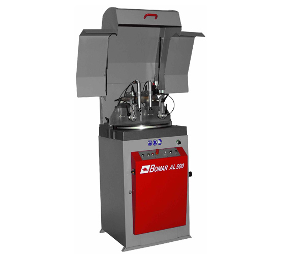
Semi-automatic circular saw for aluminum AL 500 is a machine designed for cutting of profiled and less common also full materials from aluminum alloys, copper and hard plastic. Cooling is located in its base. Saw disc diving into the cut is automatic. Angle cuts are both-sided in the range of minus 60? - 0? - 90?. Frame turning is manual. Adjustment of angle cuts can be done very easily directly from the operator’s position.
The machine has to be connected to the external input of compressed air with working pressure in the range of 0,5 - 0,6 MPa.
Note: Roller conveyors M330 can be connected to the circular saw AL 500 from the left input side (material feeding) or from the right output side (material withdrawal). The requested conveyor length can be assembled from individual modules with the lengths of 2 or 3 m. The number of supporting feet depends on the overall conveyor length.
On your request, we will be glad to send you more detailed information on the material roller conveyor product range.
Standard equipment
- Ergonomic construction of the machine with easy control.
- Smooth adjustment of cutting angles in the range of minus 60° - 0° - 90°.
- Vertical clamping cylinder Ø 40 mm.
- Electronic control of cover opening.
- Clack-valve of clamping cylinder for eventual failure of air pressure.
- Micronizer for lubrication of saw disc.
Technical description
- Machine base The saw is constructed on a robust base in a height convenient for easy material handling. The construction of this base was developed as to absorb vibrations in the broadest possible range.
- Saw disc console Tilting console is a steel welding on the pivot bolt that serves for saw disc diving into the cut.
- Saw disc Saw disc is lead to the cut via tilting console, that enables to set the size of the cut and that is embedded in bearings.
- Saw disc drive The saw disc drive is performed by a powerful 4 kW engine by means of a V-belt on the console.
- Cooling Micronizer is a standard part of the machine. This equipment has a unit in which compressed air and cutting oil are mixed. Spraying unit has three jets which spray the mixture of oil and air on the saw disc and thus prevent the leakage of cooling emulsion out of the saw. Micronizer needs external air input of 4 ATM pressure. With Micronizer it is not necessary to use common cooling emulsions, manipulate with them and solve their disposal.
- Angle cutting range The machine can be turned on both sides in the range of minus 60° - 0° - 90° directly from its front side.
- Turning console of the table Turning console is located on the ball guiding and simultaneously guided in a ground guiding segment.
- Adjustment of angle cuts Adjustment of angle cuts can be done very easily directly from the operator’s position. The saw disc is located on the turning console with possibility of firm arrest, which is adjustable by 15° and is equipped with legible angle scale.
- Material clamping The saw is by default equipped with two vertical clamping cylinders. One of them has a safe clack-valve for eventual failure of air pressure. Material is laid on adjustable boards of supporting bridge. The saw can be equipped with two horizontal cylinders for perfect clamping of material with unequal cut. Cylinders belong to optional accessories.
- Other accessories Material conveyer can be connected to the saw on the input or output side as an optional accessory. On the input side it can be equipped with firm or sliding vertical rollers that protect the material from falling. Sliding vertical rollers are suitable especially for bundle cutting.
- Saw disc speed Saw disc speed is 50m/sec. and the switch is located directly on the control panel.
- Saw disc diving into the cut Speed adjustment of saw disc into the cut is controlled via hydraulic throttling valve. Its regulation is located on the control panel.
- Control All control elements are located on the panel on the front side of the machine.
Course of working process
Working cycle is semi-automatic. The operator has to lay the material on the working table, clamp it to the board via switch on the control panel and close the safe cover. After pressing the START button the engine of the saw disc is started. For diving of the disc into the cut it is necessary to press buttons on both sides of the panel. After their release the disc goes to the lower position. Disc diving is hydraulic and its speed can be changed with control valve.
Technical data
Cutting ranges
 |
 |
 |
 |
 |
|---|---|---|---|---|
| L60°(-60°) | Ø120 mm | 120 x 70 mm | 55 x 170 mm | 115 mm |
| 0° jaws ahead | Ø170 mm | 265 x 25 mm | 90 x 175 mm | 150 mm |
| 0° jaws back | Ø135 mm | 395 x 70 mm | 375 x 95 mm | 95 mm |
| R45° (+45°) | Ø150 mm | 180 x 50 mm | 80 x 170 mm | 130 mm |
| R60° (+60°) | Ø120 mm | 120 x 70 mm | 55 x 170 mm | 105 mm |
| Total input | 5,4kVA, 16A, IP 54 |
| Material bearing height | 1060 mm |
| Chucking power | 600 N |
| Disk size | ø 500 ø 30 x 4,1 mm |
| Drive output | 4.0 kW |
| Cutting speed for disk size 400mm | 50 m/sec. |
| Dimensions: width length height |
960 mm 840 mm 1538 m |
| Total weight | 500 kg |
Description of possible accessories
- Device for horizontal material fixing Device for material bundle cutting ensures better and safer material fixing. Useful also for fixing of difficult shaped single pieces.
- Communication upgrade for M-VL In case it is necessary to connect our circular machine with other co-operating device could be machine equipped with communication set. Then is possible to connect the saw into a production line according to the customer needs.
- Connection part right/left In case of mitre cuts is not possible to connect conveyor directly to the machine, because of possible conflict between conveyor and blade at the cut finish. And space between conveyor and machine table could also make problems during material infeeding. That is why it is necessary to use connection part with removable rollers for non-conflict finishing of the cut. In case of machines without mitre cuts possibility is connection part used for conveyor fixing to the machine.
- Exhausting device Mobil Power Jet 120 Portable exhausting and filter device for exhaustion of sawdust and dust particles from one or two working places. Thanks to the size of filter input neck 120 mm (clean exhausted value for one arm 1.120m3/hour) is possible to exhaust also bigger sizes of scraps. Waste is consequently filtered with 99,9% efficiency and then returned to the working place.