
 Short description of saw and standard equipment
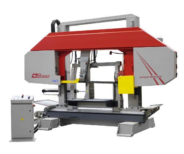
The Individual 520.360 DGANC 2300 machine is the automatic band saw of two-column design with CNC control providing possibility of automatic double angular cutting. Saw swivelling is smooth within range -60 and +60°. It is possible to clamp a cut either single pieces, or complete bunch of the material at a time by means of the hydraulic bunching machine (optional accessories). Maximal length of one feed is 2300 mm, but is individually adaptable to the customer needs between 2300mm-6000mm. The machine is equipped as standard with automatic control of band pressure to depth providing precise and straight cut beside the 34 mm saw band. The saw can be operated simply via the control panel attached to the machine base.
Standard equipment
- Two-column structure
- Saw arm is embedded on pre-tensioned linear guideways
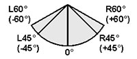
- Double-sided arm swivelling with cutting angle within range -60° to the left and +60° to the right
- Digital indicator of arm swivelling angle
- Hydraulic full-lift clamping main vice and the feeding vice
- Continuously adjustable speed of the saw band
- Very precision saw band hard-metal guideways ensure cut accuracy
- Continuously adjustable saw arm feed to depth and pressure to depth
- Automatic control of saw band pressure to depth depending on cut material resistance
- Automatic shutdown of the machine due to not tensioned or broken saw band
- Powerful and reliable saw band drive motor 3.0 kW
- Up-to-date control with the text display and the foil keyboard
- Freely positionable control panel
- Big hydraulic aggregate
- Information on machine status and automatic cycle course available via the LCD display in the form of a dialogue
- Precise feeding vice positioning by means of a sensor on a magnetic tape
- Floating seating of the feeding vice
Technical description
- Machine base The welded structure is resistant to torsion, with the incorporated cooling liquid tank and the removable chip pan.
- Saw arm The stable welded structure resistant to vibrations with the shell structure ensures very quiet run and precise cuts. The saw arm is inclined against the material bearing surface at an angle of 2°, which enables very short cutting channel for sectional materials and beams. Thanks to the short cutting channel it is possible to use finer toothing and set higher speed of feeding to depth. Service lifetime of the saw band is prolonged, cutting times significantly decrease and cut accuracy increases.
- Columns and saw arm guideways The saw arm is guided by two sturdy columns and is seated on pre-tensioned linear guideways without play. The columns are connected by means of the swivelling bracket and form stable unit with the saw arm.
- Quick arm lowering The saw arm is equipped with the height detector situated on the fast-feed stop bar. The saw runs with fast feed above the material, until the height detector goes off. Then the saw switches to the set feed value. In the automatic cycle the saw arm rises, until the height detector goes off, so that the cycle times are as short as possible.
- Swivelling bracket The swivelling bracket make automatic arm swivelling possible via chain drive. The swivelling bracket is connected to the machine base through the stationary wear-resistant bearing. The front guiding segment supports the swivelling bracket and serves for its locking. The swivelling scale is placed right on the guiding segment.
- Material clamping and feeding Material clamping using the main and feeding vices is smooth by means of the full-stroke hydraulic cylinders. Regulation of vice pressure can be used for the thin-walled materials, see optional accessories. Max. length of material feeding for one stroke is 2300 mm. The feeding vice is embedded in its total length on the pre-tensioned linear guideway. Material feed to depth is made by rack and pinion drive and controlled by frequency changer in harmony with material weight. Thanks to this regulation shorter cutting circles can be reached. The accurate position of the feeding vice is detected by means of the linear magnetic measuring system with high resolution and accuracy of 0.1 mm.
- Band tensioning The saw band is tensioned manually. Band tensioning and also possible band breaking are checked electrically. The clamping force can be set right on the saw arm with precise indication on the pressure gauge.
- Saw band guideway The saw band is put on the moving wheels and in the place of cut directed by means of the guiding cubes. The professional tree-sided hard-metal guideway of the saw band guarantees high cut accuracy and long lifetime of the saw band. The left movable cube of the saw band guideway, embedded in the holder on the prismatic guideway, is manually adjustable depending on width of the cut material.
- Saw band drive The saw band is driven by the industrial 3.0kW motor, controlled via the frequency convertor, and by the robust screw gearbox. Saw band speed can be changed continuously via the control panel within range 20–120 m/min.
- Feed to depth and control of pressure to depth Arm feed to depth is performed hydraulically by means of the hydraulic cylinder and is set on the control panel. Pressure to depth is continuously checked via the pressure-to-depth automatic control system and matched to material shape. Sensitivity of pressure-to-depth control can be adjusted individually depending on material shape and quality.
- Hydraulic system The hydraulic unit is sized to be sturdy and is located on well accessible place on the machine front side. The hydraulic system valve block is separated to make maintenance and adjustment easy.
- Controls and control system All controls of the band saw are associated on the freely positionable control panel. The saw is equipped with the up-to-date SIEMENS S7-300 control system with the large-screen graphic display and touch screen. The control system features understandable structure and enables quick access thanks to the text display and the dialogue system. Error messages and information on machine status are clearly displayed in the textual form.
Course of working process
The working cycle is automatic. The material is put on the workbench and the saw band is set with the arm over the material. After programming, 20 cutting programs are typically available, each including 20 program sentences containing data on length and number of pieces, and after pressing the START button, the material is fed by the feeding vice and then clamped via the main hydraulic vice. The band motor starts running and the arm lowers to depth. Meanwhile, the feeding vice moves to the back position for material feeding. After cut completion, the arm runs to the pre-set top position, the main vice opens and the feeding vice feeds requested length of material. The working cycle is repeated. Speed of arm feeding to depth is controlled hydraulically by means of a throttle valve. Max. possible length of feed during one working cycle is 9999.9 mm.
Technical data
Cutting range:
 |
 |
 |
 |
 |
| 90°/0° | Ø 315 mm | 520 x 315 mm | 100x325 mm | 320 mm |
| 45°R | Ø 325 mm | 520 x 315 mm | 100x325 mm | 320 mm |
| 45°L | Ø 325 mm | 365 x 315 mm | 100x325 mm | 320 mm |
| 60°R | Ø 240 mm | 235 x 315 mm | 100x325 mm | 235 mm |
| 60°L | Ø 255 mm | 255 x 315 mm | 100x325 mm | 235 mm |
| Min. vice opening | 5 mm |
| Material bearing height | 765 mm |
| Max. length of one feed | 2300 mm |
| Saw band dimensions | 4780 x 34 x 1.1 mm |
| Drive output | 3.0 kW |
| Cutting speed | 20–120 m/min. |
|
Dimensions: width |
4900 mm |
Description of possible accessories
- Angular cutting check Cutting process is checked during each cycle and the current cutting cycle is finished when the set tolerance is exceeded. The current program is interrupted and the warning light on the machine gives a signal, or the status message is displayed on the control screen.
- Device for clamping bunches The vertical hydraulic clamping unit is mounted on the feeding and main vices. This unit can be set easily by means of the easy accessible clamping units.
- Vice pressure control For cutting the thin-walled tubes and sectional materials the clamping pressure for the feeding and the main vices is controlled centrally via the control panel.
- Chip remover The generously sized grabbing chip remover transports fallen chips reliably from the machine out. Assembly attachment and connection are incorporated in the machine from the factory.
- Safety access to saw in compliance with CE directives Complete safety access to the saw within the whole area, where moving parts of the machine are present. The machine is secured from all sides by the system of the safety fencing and the luminous barriers. The luminous barriers remain active during whole operation in automatic mode and the machine is stopped each time they are interrupted.
- Single-cutting automatic system Single-cutting automatic system enables productive, fully automatic partition of single pieces. Material diameter and cut-off length are entered via the display and the material is inserted into the machine feeder area. By means of the laser detector the material is detected and the piece of specified length is cut off. If no other cuts are required, the material is released again.
- Remote administration system Thanks to internet connection provided by the customer failure and error messages are transferred to the manufacturer’s service centre. The service centre evaluates received data by return and provides for rapid and simple error remedy.
- Device Micronizer for micro-washing The micro-washing device sprays accurately adjustable minimum amount of oil-air mixture onto saw band toothing and advance. The nozzle is located right on the guiding arm and ensures ideal application of the mixture and at the same time minimum consumption of oil.
- Halogen working lamp Bright cold source of light for illumination of the band saw working site, easily adjustable via a flexible connection for necessary area.
- Gun for flushing off chips Cooling liquid is delivered by means of the incorporated pump into the flushing gun equipped with a button. Pressure is sufficient to remove chips and impurities from the material bearing surface and from the saw base.
